Dryer Cylinder/Can Dryer /Steel Yankee
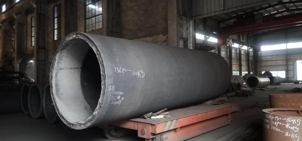
A drying cylinder is a hollow cylinder made of cast iron or steel plate welded with covers at both ends, consisting of a cylinder body and cylinder heads at both ends. The outer diameter is usually 1000-3000mm. During operation, steam is passed inside to dry the paper.
The dryer for paper machines is a key component used for drying paper – Class I pressure vessels.
The number of cast iron drying cylinders accounts for about 2/3 of the total number of pressure vessels in the paper industry. The materials commonly used for manufacturing drying cylinders are HT200 and HT250.
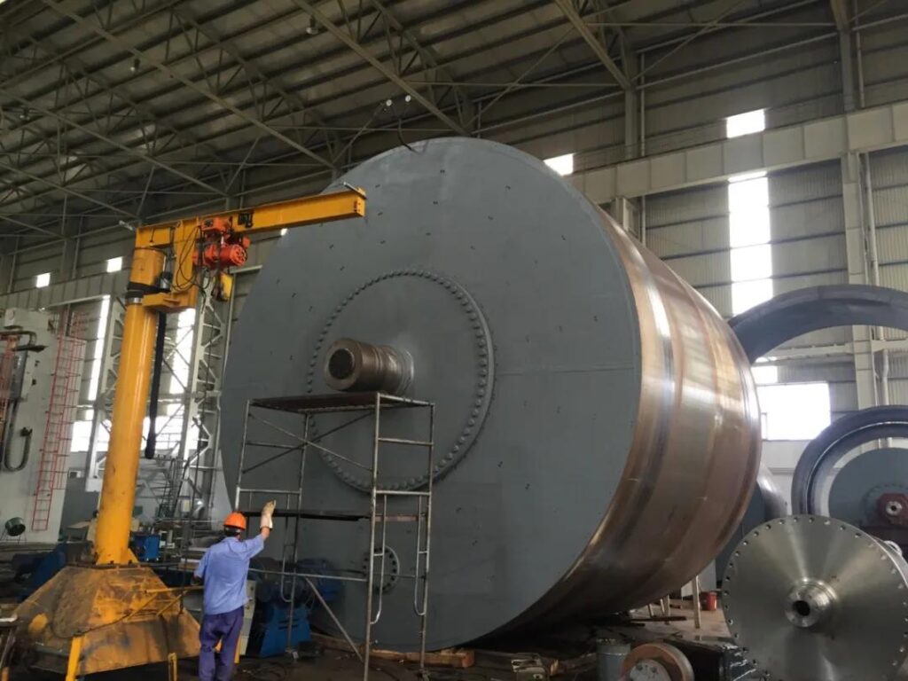
In terms of manufacturing quality, it is required that there should be no penetration or excessive sand holes.
In order to increase the smoothness of the paper surface, it is required to polish the outer surface of the dryer and smooth the inner surface, so that the entire dryer wall maintains consistent thickness to ensure the safety, balance, and uniform heat transfer of the dryer.
The function of a dryer is to dry the moisture in the paper and decorate the paper surface.
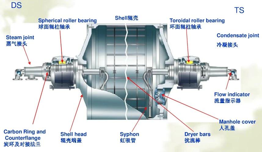
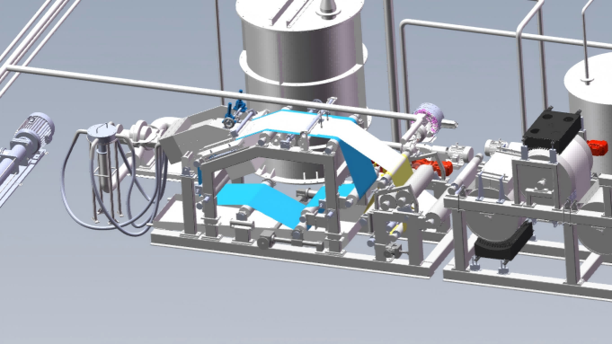
Main components
The main components of the dryer include: roller shell, turbulence bar, siphon tube, end cover, manhole cover, bearings, shaft head, steam joint, etc.
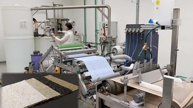
Drying principle
The saturated steam introduced from the steam joint condenses inside the dryer, releasing heat that causes the temperature of the dryer to rise, thereby heating the paper sheets running on the surface of the roller shell.
Heat is transferred to the paper through the contact between the paper and the dryer surface.
After steam releases heat and condenses, a large amount of condensed water is produced. These condensed water adhere to the inner surface of the dryer due to centrifugal force caused by the rotation of the dryer, forming a water ring at high angular velocity, which hinders the transfer of heat to the dryer surface.
Therefore, a siphon tube is needed to discharge the condensed water in a timely manner.
At low speeds, a water ring will not form, but condensation water may splash and accumulate in the dryer.
main components
Steam joint
As mentioned earlier, steam needs to be introduced into the dryer, and the condensed water inside needs to be drained. But the dryer is a rotating cylinder body, so a special joint is needed to complete this task, namely the steam joint.
The introduction of steam and the discharge of condensed water are usually completed by a rotary joint at one end of the dryer, or steam can be introduced at one end and condensed water can be discharged at the other end.
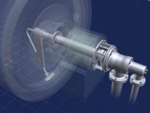
The above diagram is a typical steam joint schematic, where steam and condensate are introduced and discharged at the same end. The shaft neck at this end of the dryer is hollow, providing a passage for steam and condensate water. After entering the input end, steam enters the dryer through the opening of the conveying pipe, and condensed water is sucked up by a siphon and discharged through the pipeline, which is inside the conveying pipe.
Due to the need to install bearings and other components on the shaft neck, the temperature rise caused by steam entering the shaft neck will have adverse effects. Therefore, insulation sleeves are used to separate the heat of steam in the conveying pipe from the shaft neck as much as possible.
The insulation sleeve is fixed on the hollow shaft neck and rotates together with the dryer, while the fixed bracket, conveying pipe, etc. are stationary.
The end of the insulation sleeve should be sealed with a carbon ring to prevent internal steam leakage.
Turbulence rod
The purpose of the turbulence bar is to disrupt the condensate water ring formed in the dryer under high-speed rotation, generating more turbulence. The turbulence bar is installed on the horizontal direction of the inner surface of the dryer, and it rotates at a constant speed with the dryer. Therefore, it will move the water ring, generate turbulence, and facilitate heat conduction. Draw the position of the turbulence bar in the dryer structure diagram.
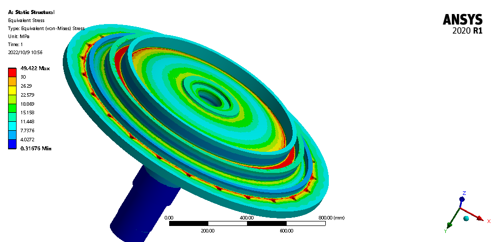
Finite Element Analysis of Dryer Cylinder

Frequently Asked Questions
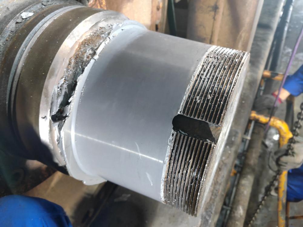
Drying cylinder shaft head wear
Due to the high temperature and pressure experienced by the dryer during operation, the dryer shaft head is prone to wear and tear, resulting in the equipment being unable to operate.
The traditional repair method is to process non-standard sleeves for repair, which can easily lead to problems in the combination of non-standard sleeves and shaft diameters; Dismantling, machining, and repairing have long construction periods and high costs.
For many years, enterprises have been unable to find effective and fast repair methods. The mature fast repair methods in China mainly use polymer composite materials for on-site fast repair, which far exceed traditional repair methods such as welding and brush plating in terms of repair effect and cost.
The repair time is fast, the process is simple, and the cost is relatively low. Polymer composite materials not only ensure 100% contact between their mating surfaces, but also possess inherent resilience, making their ability to resist impact and vibration much higher than that of non yielding metal materials.
At the same time, they expand and contract with the expansion and contraction of the bearing inner ring, minimizing the possibility of wear and ensuring the normal operation of the equipment, even beyond its normal service life.
Operation Method:
1. Mold processing: making standard split molds (double-sided or single-sided positioning);
2. Surface treatment: degreasing, polishing, cleaning to ensure a clean, dry, and sturdy surface;
3. Mixing materials: accurate proportion, uniform mixing;
4. Coating material: Ensure adhesion, filling and thickness;
5. Install mold: Apply release agent, install and fix to ensure excess material is squeezed out;
6. Demolding: After solidification, dismantle the mold to clean up excess materials. The materials should not be knocked and can be removed using tools such as polishing machines and files to meet installation requirements.