
Analysis and Exploration of the Effectiveness of Inspection for Cast Iron Dryer Cylinders and Their Safety Protection Devices
Cast iron dryer cylinders represent a relatively niche and specialized type of pressure vessel. Their structural characteristics,
material properties, safety protection devices, design and manufacturing standards, and failure modes differ from those of traditional steel pressure vessels.
In light of this, this paper conducts a targeted analysis using gray cast iron dryer cylinders for the paper industry as an example.
It proposes strategies for scientifically effective inspection, which can help avoid liability incidents caused by the mechanical application of codes and standards.
Implementation Standards
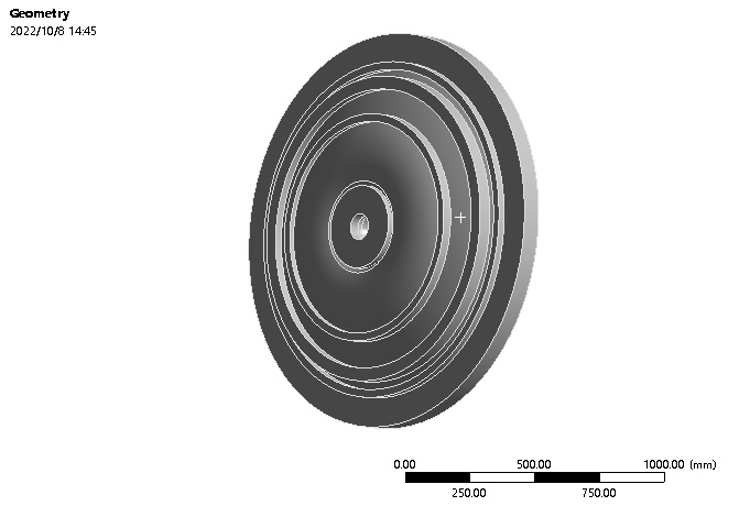
Cast iron dryer cylinders are cylindrical heat exchange vessels installed in fixed positions and rotating about a horizontal axis,
with a structure as shown in Figure 1.
During operation, steam is introduced into the cylinder body, typically used in the paper industry for smoothing paper.
Finally, condensate is discharged from the cylinder via a syphon pipe through a drain valve.
Therefore, cast iron dryer cylinders fall under the category of pressure equipment regulated by the *Special Equipment Safety Law.
In recent years, explosions of cast iron dryer cylinders have been reported from time to time.
Related issues
In Document No. 31 [2016] from the Special Equipment Safety Supervision Bureau of the former General Administration of Quality Supervision.
Inspection and Quarantine, “Notice on Strengthening Safety Supervision of High-Risk Boilers and Pressure Vessels”,
dryer cylinders were explicitly classified as high-risk.
Related issues
Requiring inspection according to the special equipment safety technical specification TSG 21—2016 *”Safety Technical Supervision Regulation
for Stationary Pressure Vessels”* (hereinafter referred to as the “Pressure Vessel Regulation”).
Related issues
They can only be used if their safety condition meets the requirements.
Gray cast iron is commonly used to manufacture paper dryer cylinders. It is a brittle material with lower tensile strength, plasticity,
and toughness compared to the steels commonly used for pressure vessels.
Apart from their use in dryer cylinders, there are no reports of gray cast iron being used to manufacture other pressure vessels.
Testing of cast iron drying cylinders
The author has reviewed relevant textbooks prevalent in the pressure vessel inspection industry,
none of which provide detailed descriptions for inspecting cast iron dryer cylinders.
The material properties, manufacturing processes, and stress distribution (involving rotational motion) of cast iron dryer cylinders differ from those of typical steel pressure vessels.
Related issues
Furthermore, their main body and primary pressure-bearing components lack safety attachments.
These circumstances pose challenges to the effective implementation of inspections for cast iron dryer cylinders.
This paper analyzes and explores the intrinsic safety of cast iron dryer cylinders and, based on the author’s years of practical experience,
attempts to propose practical and effective inspection strategies, thereby providing technical support and assurance.
1. Characteristics of Cast Iron Dryer Cylinders
1.1 Common Materials for Cast Iron Dryer Cylinders
Cast iron is a multi-component iron alloy based on iron, containing elements such as carbon, silicon, manganese, phosphorus, and sulfur.
Internationally, chemical composition is not the basis for acceptance of castings;
instead, castings must meet the mechanical properties and microstructure requirements specified in material standards.
Related issues
China has long mastered advanced cast iron smelting processes.
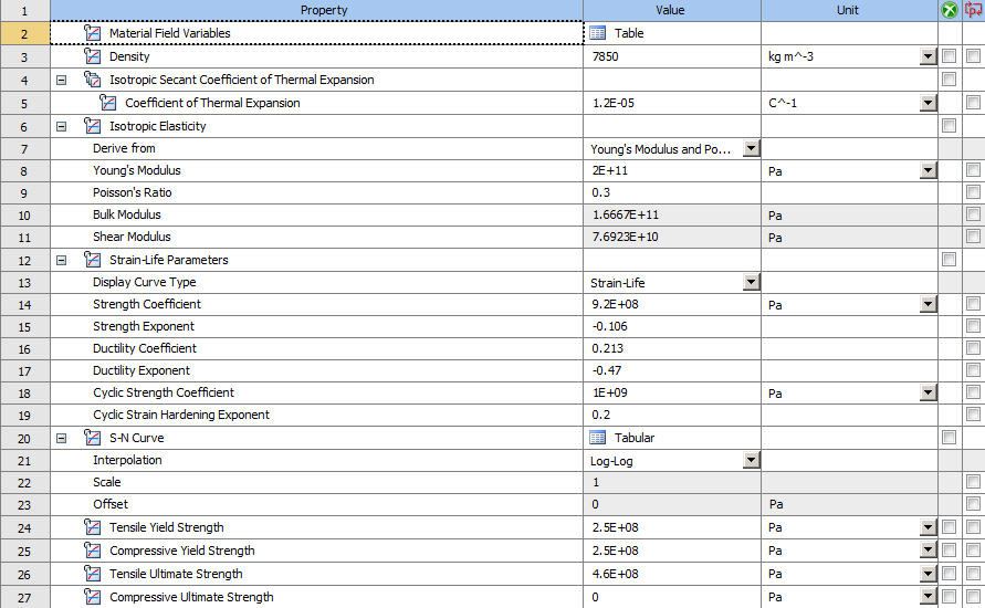
Currently, gray cast iron grades HT200 and HT250 are commonly used for paper dryer cylinders.
Their mechanical property parameters are shown in Table 1.
Their microstructure consists of pearlite (matrix) + flake graphite.
Since graphite has higher thermal conductivity than pearlite, gray cast iron possesses good thermal conductivity.
Related issues
Additionally, gray cast iron melt has good fluidity, with low linear and volumetric shrinkage during solidification, making it less prone to cracking.
Meanwhile, the presence of flake graphite reduces the notch sensitivity of gray cast iron, making cracks less likely to propagate rapidly compared to steel.
Related issues
According to the high-temperature mechanical performance curve of gray cast iron, its mechanical properties change little from room temperature to 400°C.
Below 350°C, gray cast iron is very stable, with almost no oxidation or growth.
Related issues
Note: ① In the 1999 edition of the *”Safety Technical Supervision Regulation for Pressure Vessels”*, the allowable design temperature for gray cast iron was 0–250°C.
Gray cast iron is hard, wear-resistant, and has high stiffness. Cylinders cast from it have better roundness compared to those rolled from steel plates.
Its corrosion resistance in the atmosphere is superior to carbon steel. Particularly during smoothing, paper can easily peel off its surface.
Product Summary
For these reasons, gray cast iron has always been the preferred choice for manufacturing paper dryer cylinders.
However, gray cast iron resists compression but not tension.
To ensure safety, the *Pressure Vessel Regulation* adopts the method of increasing redundancy, stipulating that the safety factor for tensile strength at room temperature should not be less than 10.0 when gray cast iron is used for pressure vessels.
1.2 Operating Conditions of Cast Iron Dryer Cylinders
The pressure-bearing parts of a cast iron dryer cylinder are the cylindrical shell, the two end covers, and the connecting bolts between the covers and the shell.
The supporting components are the rotating shaft at the center of the covers and the machine frame base.
Related issues
The common outer diameters for papermaking cast iron dryer cylinders are the 1,800 mm and 2,000 mm series.
With shell lengths mostly ranging from 2,000 to 6,000 mm. The design allowable parameters are shown in Table 1.
1.3 Safety Protection Devices for Cast Iron Dryer Cylinders
According to publicly available domestic accident investigations, explosions of cast iron dryer cylinders are basically caused by overpressure operation [1].
Generally, steam generated by the boiler house is supplied to various production sections in the factory.
However, the steam pressure required for cast iron dryer cylinders is often lower than that for other sections.
Related issues
If no overpressure automatic relief device is installed on the steam supply pipeline before the cylinder’s steam inlet, overpressure accidents are highly likely to occur.
Furthermore, the steam inside the cylinder needs to be supplied continuously, safely, and stably to ensure production operation.
Product Summary
Therefore, a pressure-reducing device must be installed before the overpressure automatic relief device to achieve safety redundancy. Installation can be done as shown in Figure 2.
The electric contact pressure gauge in the figure can be connected to the boiler control system to achieve overpressure interlock protection.
To prevent impurities from flowing in and causing the pressure-reducing valve to jam or malfunction, a filter must be installed before the pressure-reducing valve.

Related issues
The pressure-reducing valve is the core component of the safety protection device. From a fluid dynamics perspective, it is a throttling element with variable local resistance.
By changing the throttle area, the flow velocity and kinetic energy of the fluid are altered, creating different pressure losses to achieve pressure reduction.
Then, relying on the regulation of the control and regulation system, the fluctuation of the downstream pressure is balanced with the spring force, maintaining a constant value within a certain error range.
Related issues
Based on their operating principle, pressure-reducing valves can be categorized as pilot-operated or direct-acting.
The structure of a pilot-operated pressure-reducing valve is shown in Figure 3.
During use, the cap is removed, the lock nut is loosened, and the adjusting screw is turned clockwise.
The adjusting spring is compressed, pushing the diaphragm downward, opening the pilot valve core.
Related issues
The medium passes through the pilot valve core, flows along the pilot hole to the top of the main valve piston,
pushing the piston downward, which drives the main valve core to open.
The downstream pressure begins to rise. This downstream pressure passes through the pilot hole in the main valve body to the lower side of the pilot diaphragm.
Related issues
When it balances with the adjusting spring force, both the pilot and main valve cores maintain a certain opening, keeping the outlet pressure stable.
When the outlet pressure rises, the pressure on the lower side of the pilot diaphragm increases accordingly, causing the diaphragm to move upward.
The pilot valve core tends to close under the action of the pilot spring, reducing the medium pressure flowing to the top of the main valve piston.
Related issues
The main valve core gradually closes under the main valve spring, causing the downstream pressure to drop back to the set value.
When the outlet pressure drops, the pressure on the lower side of the pilot diaphragm also drops.
Related issues
Under the adjusting spring force, the diaphragm moves downward, the pilot valve core tends to open.
The medium pressure flowing through the top of the main valve piston increases,
the piston pushes the main valve core to open wider, causing the downstream pressure to rise and return to the set value.
Related issues
The structure of a direct-acting pressure-reducing valve is shown in Figure 4.
During use, the adjusting screw inside the cap is turned clockwise, compressing the pressure-adjusting spring,
which pushes the diaphragm and valve stem downward, opening the valve core.
Related issues
Steam is output at the outlet. Simultaneously, the output pressure acts on the diaphragm through feedback, generating an upward thrust.
When this thrust balances with the pressure-adjusting spring force, the output pressure stabilizes.
Clearly, pilot-operated pressure-reducing valves are much more sensitive, reliable, and have a higher pressure reduction ratio than direct-acting ones.
2. Production Standards for Cast Iron Dryer Cylinders
In April 1988, China’s former Ministry of Light Industry first promulgated ZB Y91 003—1988 “Technical Conditions for Cast Iron Dryer Cylinders for Paper Machinery”
The following year, ZB Y91 008—1989 *”Design Rules for Cast Iron Dryer Cylinders for Paper Machines”was promulgated.
These two standards were revised in 2002 and 2008 respectively.
In 2021, the two standards were merged into one, namely QB/T 2551—2021 “Cast Iron Dryer Cylinders for Paper Machinery”.
Related issues
Since its promulgation, this standard (hereinafter collectively referred to as the “cast iron dryer cylinder product standard”) has been used for the design, manufacturing, and factory inspection of papermaking cast iron dryer cylinders.
Therefore, this standard should serve as an important reference for studying effective inspection.
3. Implementation and Effectiveness Analysis of Inspection Items for In-Service Cast Iron Dryer Cylinders
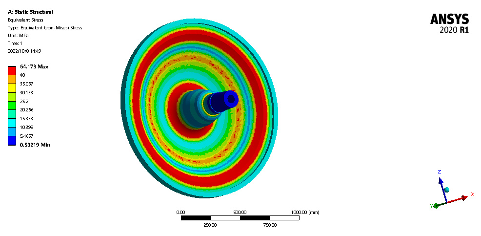
Conducting stress analysis, corrosion analysis, material degradation analysis, etc., on dryer cylinders is a prerequisite for implementing effective inspection.
During operation, the end covers not only withstand internal pressure but also the self-weight of the cylinder shell.
Moreover, due to the continuous rotation of the shell, the covers are constantly subjected to cyclic stress, which can easily lead to fatigue.
Related issues
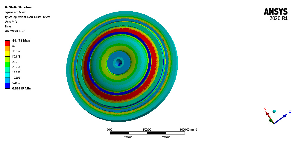
Temperature differential stress exists between the inner and outer walls of the cylinder.
When the drainage system fails, condensate subjected to centrifugal force can cause bending stress.
Therefore, cracks are prone to initiate in areas of stress concentration.
Related issues
Such as around the shaft holes of the covers, around manhole rings, and in the shoulder area of the cylinder shell (Figure 1).
Simultaneously, these discontinuous areas often tend to have manufacturing defects like porosity and shrinkage cavities.
After a certain period of use, cracks may also accompany these original manufacturing defects.
Related issues
If internal laminations exist in the cast iron during manufacturing, localized spalling may occur at these lamination sites after long-term use.
The inner surface, in contact with steam, may suffer from erosion.
The outer surface, in contact with damp paper, may undergo corrosion from moisture, acids, alkalis, as well as mechanical abrasion from the paper.
To maintain the surface smoothness, the user may grind the outer surface of the cylinder shell. All these factors can lead to wall thickness reduction.
Related issues
Long-term operation of gray cast iron at excessive temperatures may cause changes in graphite morphology (type), shortening of graphite flakes, micro-cracks at flake tips, a decrease in pearlite content,
and an increase in carbide and phosphide eutectic content, affecting the material’s mechanical properties.
3.1 Document Review
Firstly, the cast iron material grades that can be used for manufacturing dryer cylinders are explicitly specified in the *Pressure Vessel Regulation.
Secondly, material standards for gray cast iron used in paper dryer cylinders, across various editions, stipulate that products with defects affecting service performance,
such as cracks, cold shuts, and shrinkage cavities, are not allowed to leave the factory.
Related issues
China has long implemented a manufacturing supervision and inspection system for pressure vessels.
Products meeting the requirements of special equipment safety technical specifications are issued supervision and inspection certificates before they can leave the factory for installation and use.
Related issues
Therefore, for cast iron dryer cylinders undergoing their first inspection after being put into service, their factory documentation should first be reviewed for completeness.
The nameplate information and external dimensions of the actual cylinder should be checked against the supervision certificate, as-built drawings, and other factory documents.
Related issues
Material certificates should be verified to determine if the material and design parameters comply with the Pressure Vessel Regulation
and the cast iron dryer cylinder product standard applicable at the time of manufacture.
3.2 Macro Inspection
During the first periodic inspection, the structure and geometric dimensions should be inspected.
Focusing on whether the geometric parameters of discontinuous areas comply with the stipulations of the cast iron dryer cylinder product standard.
If repairs have been made, the repaired areas and patched holes should be inspected for compliance with the product standard and checked for induced cracks.
Related issues
Visually inspect the inner and outer surfaces of the cylinder for defects such as cracks, porosity, shrinkage cavities, spalling, erosion, and wear.
Discontinuous structural areas and repaired locations can be carefully examined using a magnifying glass and a flashlight with adequate brightness.
Related issues
For the bolts on both end covers, a sampling method (e.g., two bolts each from top, bottom, left, and right) can be used to check for cracks.
Studs of M36 and above should be individually cleaned and inspected for cracks.
Check if a large amount of condensate has accumulated inside the cylinder, if the syphon pipe is blocked or loose, and if the drainage device is intact.
Related issues
Inspect various sealing locations on the cylinder (cover-to-shell, manhole-to-cover) for signs of leakage.
If inspectors cannot enter the cylinder interior, an endoscope can be used.
3.3 Hardness Check
Gray cast iron exhibits almost no yield stage under tension.
There is a linear relationship between its hardness and tensile strength.
Measuring the hardness value allows inference of whether the tensile strength meets requirements.
Related issues
If the hardness value exceeds the upper limit of the standard, material aging may have occurred.
A decrease in total carbon content or a transformation of graphite from Type A to Type D can significantly increase hardness.
Related issues
Further metallographic examination and NDT should be conducted.
A decrease in hardness may indicate wall thickness reduction, warranting further ultrasonic thickness measurement.
This is because during casting, the outer wall cools faster, resulting in finer grains, while the center cools slower, resulting in coarser grains.
Related issues
The microstructure (e.g., graphite shape, size) varies to different degrees at different wall thicknesses, leading to variations in mechanical properties.
Hardness tends to be lower closer to the cylinder center.
Related issues
Hardness testing method: The surface roughness at the test location should reach 2 μm.
Test points should be selected within 80–100 mm from each end of the cylinder shell, avoiding the joint area between the shell and end covers.
Related issues
Test two points at each end.
The arithmetic average of the four measured points is taken as the cylinder surface hardness value.
Acceptance criteria for hardness can refer to Table 2.

Note: The hardness difference between the two ends of the cylinder surface should be ≤ HB24.
3.4 Wall Thickness Measurement and Strength Verification
To determine if the remaining wall thickness still meets pressure-bearing strength requirements, ultrasonic thickness measurement is commonly used.
However, gray cast iron has coarse grains, and the flake graphite causes discontinuity in the matrix structure.
Therefore, ultrasonic attenuation in gray cast iron is significant. Ordinary digital thickness gauges may fail to obtain readings.
Related issues
Typically, a digital thickness gauge with A-scan display and a low-frequency, large-crystal diameter straight probe should be used.
Adjust the gain and use the primary and secondary bottom echoes displayed on the screen to verify the accuracy of the thickness reading.
Note: The lower the probe frequency, the poorer the sound beam directivity and the larger the pulse width, resulting in wider echo waveforms and lower resolution on the instrument display.
Related issues
The larger the crystal diameter, the longer the near-field zone.
If the near-field zone length exceeds the workpiece thickness, the instrument may also fail to display a thickness reading.
Experiments show that using a straight probe with a frequency of 1 MHz and a crystal diameter of 13 mm yields good results.
Related issues
Different grades and thicknesses of gray cast iron have varying carbon contents.
Lower carbon content leads to faster sound speed, and the outer wall also has faster sound speed than the center.
Related issues
Therefore, the sound speed generally differs for different gray cast iron dryer cylinders.
Before thickness measurement, a caliper can be used to measure the thickness at the edge of the cylinder shell,
and then the thickness gauge can be used to calibrate the sound speed at that location before starting measurements.
The sound speed range for cast iron is 4,100–5,000 m/s.
Related issues
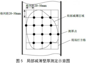
Typically, take cross-sections along the axis of the measured cylinder shell at the symmetrical center and on both sides.
On each cross-section, distribute 4 thickness measurement points evenly.
If local thinning is found, a grid method (Figure 5) can be used to define the thinned area.
Repair welding is not allowed for cast iron dryer cylinders.
3.5 Surface Nondestructive Testing
Areas suspected during macro inspection and stress-concentrated discontinuous regions should undergo 100% magnetic particle testing.
During testing, the surface condition, illumination, and testing procedure of the inspected area should comply
with the requirements of the relevant standard [need reference document number from original text] to ensure detection rate.
3.6 Hydrostatic Test and Acoustic Emission Testing
The hydrostatic test can assess the overall strength and sealing performance of the dryer cylinder while also creating a closing effect on micro-cracks, blunting their tips.
When internal inspection of the cylinder is difficult, the hydrostatic test is an effective inspection method
and can be conducted in conjunction with acoustic emission (AE) testing. AE testing can monitor whether the cylinder has active defects.
Related issues
If Grade III or IV located sources are detected, pressurization should be stopped, and conventional NDT methods should be used to verify the existence of defects at the source locations.
Related issues
Currently, gray cast iron HT250 can be tested and evaluated according to reference document [need reference document number from original text].
If no significant anomalies are detected by AE, slowly increase the pressure to 2 times the allowable working pressure,
hold for 30 minutes, then reduce to the allowable working pressure and hold for another 30 minutes for inspection.
Related issues
During the inspection period, the pressure should remain constant, with no leakage, abnormal noise, or visible deformation, for the test to be considered qualified.
Related issues
Before the hydrostatic test, the allowable working pressure corresponding to the measured minimum wall thickness of the cylinder should be confirmed to ensure safety.
The test water temperature should not be below 5°C.
Related issues
Effective measures should be taken before the test to ensure the connecting shaft is not affected by the water’s own weight,
the supporting fixture is secure, and water should be completely drained after the test.
3.7 Inspection of Safety Protection Devices
The pressure-reducing valve is a critical component unique to ensuring cast iron dryer cylinders do not operate under overpressure.
However, due to its installation location not being on the cylinder itself, it is often overlooked during cylinder inspection, ultimately leading to accidents.
Pressure-reducing valves larger than DN50 are considered pressure piping components.
Related issues
According to reference document [need reference document number from original text], they should undergo type testing.
Pressure-reducing valves without a type test certificate must not be used for special equipment.
The nameplate information should be checked against requirements, verifying suitability for the medium,
and whether the inlet and outlet pressure ranges meet operational needs.
Related issues
Inspect the valve body surface for damage, rust, or deformation. Before putting the cylinder into operation, observe if the outlet pressure meets requirements.
If the outlet pressure still does not meet requirements after adjustment,
the valve should be disassembled for further inspection of wear between the disc and seat, and whether the spring is deformed or damaged.
Related issues
The filter before the pressure-reducing valve should be regularly cleaned and maintained.
Clean steam is essential for ensuring the reliable operation and extended service life of the pressure-reducing valve.
Related issues
Full-lift safety valves meeting the requirements of reference document [need reference document number from original text] should be used and regularly calibrated as required.
The set pressure must not exceed the allowable working pressure of the dryer cylinder.
Its flow path diameter should meet the discharge capacity requirements specified in reference .
During production operation, manual blow-down tests should be conducted periodically to prevent failure.
4. Conclusion
Cast iron dryer cylinders are unconventional pressure vessels.
By analyzing their inherent characteristics and selecting scientifically effective inspection methods,
we can avoid blind and mechanical application of safety technical specifications.
This ensures inspection quality from a fundamental perspective, provides technical support for enterprise safety production, and reduces risks.