
Introduction to Shoe Press Systems in High-Speed Toilet Paper Machines
Toilet paper machine the increasing speed places higher demands on the dehydration performance of the pressing section.
The application of shoe press systems significantly improves the dewatering performance of toilet paper machines under high-speed operating conditions.
1. Shoe Press System
Shoe press technology is one of the latest technologies in the toilet paper production field.
The shoe press system transforms dynamic dewatering under instantaneous narrow pressure rolls (line contact) into static dewatering under long-term wide pressure rolls (surface contact).
Its shape, combined with the opposite pressure rolls (Yanke dryers), forms very wide pressure rolls, making it a wide-roll press.
Related information
Compared to conventional presses, the width of the pressure rolls in a shoe press is several times larger.
At the same machine speed, the residence time of the paper web in the shoe press rolls is several times longer than that in a conventional press,thus providing a longer dewatering time.
Related information
Therefore, the dryness of the paper web exiting the press is improved, while the bulkiness is maintained.
Meanwhile, shoe presses can achieve higher linear pressures, far exceeding those of traditional roller presses.
This results in more uniform dewatering of the paper web, better crease control in thin paper, and reduced rewetting.
Related information
Therefore, shoe presses help improve paper web dewatering efficiency, promote better paper web compaction,
and allow the paper web to achieve better strength and bulk before drying, thus improving the operating performance of the press section.
Furthermore, the reduced moisture content of the paper web also significantly saves on steam or natural gas consumption.
2. Toilet Paper Machine NipcoFlex T Shoe Press Structure
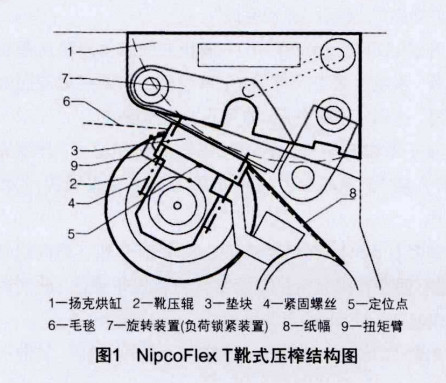
The NipcoFlex T shoe press is a type of single-cantilevered shoe press, mainly composed of the shoe roll, load locking mechanism, and some auxiliary components (see Fig. 1).
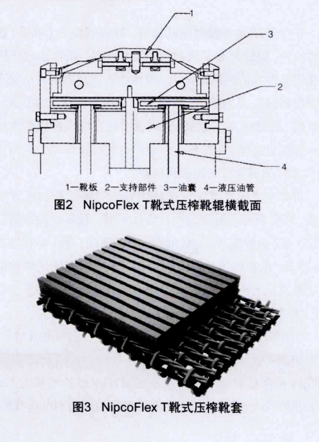
The main components of the shoe roll include the shoe beam, rotating head, cross beam, bearing housing, etc. (see Fig. 2).
The sleeve mounted on the shoe roll is a flexible material called the shoe sleeve (see Fig. 3).
The shoe roll itself has no drive unit. The shoe roll core (the shoe beam) is stationary and does not rotate.
The shoe sleeve mounted on the shoe roll is the rotating component. The shoe sleeve is installed via clamping rings onto special bearings at both ends of the roll core.
The shoe beam is the core part of the shoe press, fixed on the beam inside the shoe roll.
Related information
Under the action of the oil chambers, the shoe beam applies pressure towards the counter roll (Yankee dryer).
The hydraulic oil inside the shoe sleeve creates a layer of high-pressure oil film between the shoe beam and the shoe sleeve.
Supported by hydrostatic and hydrodynamic principles, this high-pressure oil film supports, lubricates, and cools the shoe beam and the shoe sleeve.
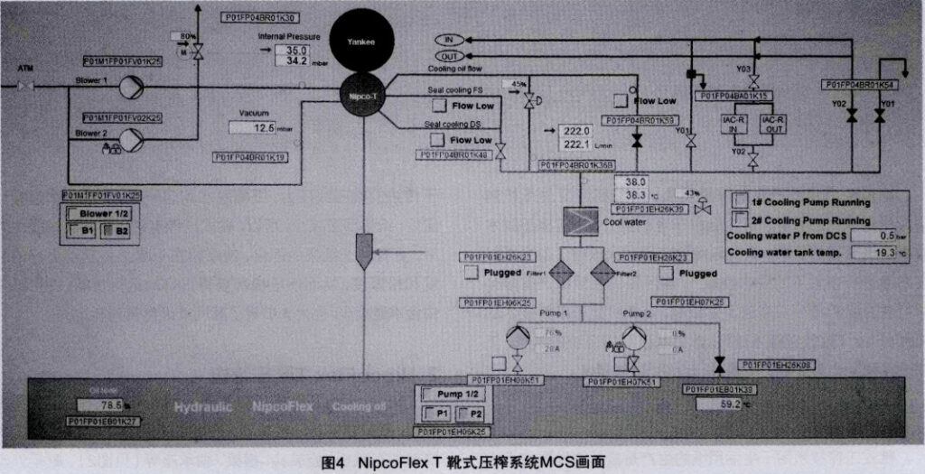
The shoe sleeve is primarily composed of polyamide and polyurethane with good resistance to acids and alkalis.
The surface of the shoe sleeve is generally designed with groove patterns.
Key indicators for the shoe sleeve include sleeve thickness, groove width, groove spacing, groove depth, open area ratio, and water holding capacity.
Certainly, the shoe sleeve material and manufacturing process are also among the main key indicators affecting its service life.
2.1 Toilet Paper Machine Workflow
The Mechanical Control System (MCS) screen for the NipcoFlex T shoe press system is shown in Fig. 4. In this shoe press system, the linear pressure at the inlet and outlet of the shoe press is controlled by setting the Nip Linear Pressure and the Shoe Beam Tilt.
This, in turn, sets the pressure in the shoe press oil chambers.
Commands are sent to the proportional valve K36 in the shoe press oil circuit to control the actual pressure in the oil chambers.
Related information
The deformation of the oil chambers is reflected by the stroke.
This shoe press system mainly involves six working processes: “Oil Filling,” “Oil Warming,” “Hydraulic System Start,” “Lock,” “Close,” and “Load,” as detailed below.
Oil Filling: After a new shoe sleeve is installed on the shoe roll, and there is no oil inside the shoe press, an oil filling operation for the shoe press system is required.
The filling process can be completed automatically after the command is given, displaying “Oil Filling Complete.”
Oil Warming: The temperature of the hydraulic oil is crucial for the shoe press system.
The system has temperature interlock protection. Before starting the system, the hydraulic oil must undergo a warming process.
The hydraulic system can only be started after the set conditions are met.
Hydraulic System Start: After warming is completed, the “Blower” and “Hydraulic Oil Pumps” need to be started to initiate the hydraulic system. Valve K48 opens.
Lock: Under the action of the cantilever hydraulic cylinders, the shoe press roll is lifted towards the Yankee dryer,
and the locking structure fixed on the frame locks the shoe press roll in place.
At this point, there is a certain gap between the shoe press roll and the Yankee dryer; they are not in contact.
Close: When the machine speed reaches 500 m/min and other operating conditions are met, the “Shoe Press Close” operation can be performed.
Valves K54-Y01 and K54-Y02 open, valve K59 opens, and oil begins to enter slightly.
At this point, the shoe press roll is pressed tightly against the Yankee dryer.
Load: After the loading conditions are met (controlled by the pressure difference between the shoe press inlet and outlet),
the “Shoe Press Load” operation can be performed. Valve K15-Y01 opens, valve K54-Y01 closes;
Valves K15-Y02/Y03 open, valve K54-Y02 closes; Valve K59 closes, and the proportional valve K36 opens.
The oil inlet flow is regulated according to the set linear pressure value to achieve shoe press loading.
2.2 Issues Related to Production Practice
Hydraulic Oil Temperature: The hydraulic oil temperature is crucial for the shoe press system. The system has temperature interlock protection.
Generally, the oil tank temperature and the shoe press roll inlet temperature are controlled within the ranges of 35–65°C and 30–45°C, respectively.
Coolers are equipped on the oil circuit, allowing control of the hydraulic oil temperature by adjusting the cooling water temperature and pressure.
Related information
Hydraulic Oil Pressure: The oil pressure directly affects the deformation of the shoe press oil chambers and indirectly influences the pressure stability at the contact surface between the shoe press and the Yankee dryer.
The pressure at the outlet of the hydraulic oil pump is maintained at around 1.8 MPa.
It is automatically adjusted via the inlet hydraulic oil flow proportional valve to control the oil chamber pressure in the machine direction (inlet/outlet) of the shoe press system.
Related information
In practice, the filter at the pump outlet significantly affects oil pressure stability and needs regular cleaning to ensure stable oil pressure.
Loading Pressure: The loading pressure of the shoe press can be measured by tension sensors on the cantilever.
This pressure is generally around 140 kN/m. The loading pressure can be adjusted by setting the Shoe Press Linear Pressure value (70–90 kN/m) and the Shoe Beam Tilt value (1–5).
Related information
In actual production, the linear pressure and tilt values significantly impact paper bulk and drying energy consumption.
By setting different values to adjust the loading pressure, a balance between paper bulk and drying energy consumption can be achieved.
Oil Chamber Stroke: The oil chamber stroke data directly reflects the deformation of the oil chambers themselves.
Related information
The system detection points are at the drive side, operation side, and center positions, generally within 19–21 mm.
The deformation of the oil chambers, i.e., changes in stroke data, is mainly related to the shoe beam, the initial position of the Yankee dryer, and the Yankee dryer’s roundness.
In practice, the thickness of the shoe press packing blocks needs to be adjusted based on the felt thickness.
Measures such as stabilizing the Yankee dryer pressure and maintaining its roundness help reduce the impact of stroke data variations on paper drying.
3. Conclusion
In the energy-intensive industry, high-speed tissue machines face pressure from energy competition.
Efficient and energy-saving machine types are the trend of development.
The application of innovative and efficient new technologies will minimize energy consumption and help improve enterprises’ comprehensive competitiveness.
Related information
Therefore, researching the internal structure, working principle, and control logic of the NipcoFlex T shoe press system for high-speed tissue machines is very necessary.
Simultaneously, how to optimize its operation, maximize the effectiveness of the shoe press system,
reduce production costs, and improve the quality of tissue base paper requires relentless exploration and practice by every production technician.